![]()
![]()
|
|
|
The C800's front panel appears as follows:
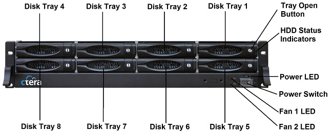
The front panel's interior contains the following elements:
Element |
Description |
|||||
Disk Tray 1-8 |
Eight disk trays for installing hard drives. |
|||||
Tray Open Button |
Each disk tray has a Tray Open Button, which serves the following purposes:
|
|||||
HDD Status Indicators
|
Each disk tray has two LEDs that indicate its status: |
|||||
LED |
State |
Explanation |
||||
Upper LED |
Blinking (Blue) |
Disk activity |
||||
Lower LED |
On (Green) |
OK |
||||
|
On (Red) |
Disk failure |
||||
|
Blinking (Red) |
RAID array failure |
||||
Power LED
|
A LED indicating whether the system is operational: |
|||||
State |
Explanation |
|||||
On (Green) |
The system is operational. |
|||||
Off |
The system is not operational. |
|||||
Power Switch |
A switch used for turning the appliance on and off and resetting it. The switch is covered by a clear plastic cover that must be lifted in order to access it. |
|||||
Fan 1 LED / Fan 2 LED
|
A LED for each fan, indicating whether the fan has failed: |
|||||
State |
Explanation |
|||||
On (Red) |
The fan has failed. |
|||||
Off |
The fan is operational. |
|||||
See Also |