![]()
![]()
|
|
|
Network and power connections are made via the appliance's rear panel.
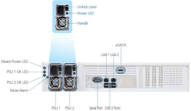
The appliance rear panel contains the following elements:
Element |
Description |
|||
Device Power LED
|
A LED indicating whether the appliance is operational: |
|||
State |
Explanation |
|||
On (Green) |
The appliance is on. |
|||
Off |
The appliance is off. |
|||
PSU 1 / PSU 2 |
The appliance's power supplies. |
|||
PSU Power LEDs
|
A LED for each power supply, indicating whether it is operational: |
|||
State |
Explanation |
|||
On (Green) |
Input power detected. |
|||
Off |
No input power. |
|||
PSU Unlock Levers |
A lever for each power supply, enabling one to unlock it. |
|||
PSU 1 OK LED /
|
A LED for each power supply, indicating whether it is in use: |
|||
State |
Explanation |
|||
On (Yellow) |
The power supply is in use. |
|||
Off |
The power supply is not in use. |
|||
PSU Handles |
A handle for each power supply, enabling one to remove it. |
|||
Mute Alarm |
If both power supplies are installed, and one of the power supplies fails or loses power, an alarm signal will sound. Press this button to mute the power supply alarm. |
|||
Serial Port |
A serial (RS-232) console port used for connecting to the appliance console. The console can be used for advanced troubleshooting and maintenance operations. |
|||
USB 2.0 Ports |
Four USB 2.0 ports used for connecting USB drives. Note that you can connect more than four USB drives, by connecting a powered USB hub. Be sure to use a powered hub, in order to avoid exceeding the power capacity of the USB ports. |
|||
eSATA |
An eSATA port used for connecting the appliance to a SATA drive. |
|||
LAN 1 / LAN 2 |
Two Ethernet ports used for connecting the appliance to your Ethernet LAN switch or router. Connect the Ethernet cables provided in the appliance package to these ports. To use both ports in parallel, configure link aggregation, as described in Enabling/Disabling Link Aggregation. For best performance, use a Gigabit-capable Ethernet switch. |
|||
See Also |