![]()
![]()
|
|
|
The C400's front panel appears as follows:
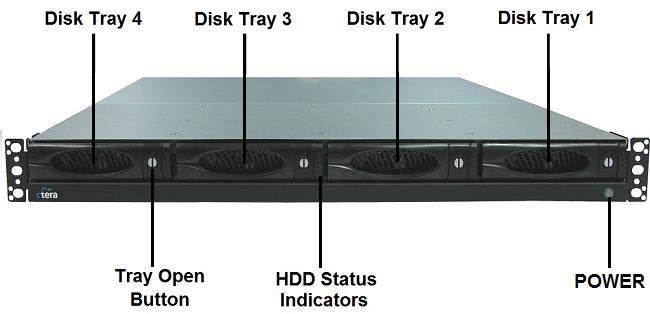
The front panel's interior contains the following elements:
Element |
Description |
|||||
Disk Tray 1-4 |
Four disk trays for installing hard drives. |
|||||
Tray Open Button |
Each disk tray has a Tray Open Button, which serves the following purposes:
|
|||||
HDD Status Indicators |
Each disk tray has two LEDs that indicate its status: |
|||||
|
LED |
State |
Explanation |
|||
|
Upper LED |
Blinking (Blue) |
Disk activity |
|||
|
Lower LED |
On (Green) |
OK |
|||
|
|
On (Red) |
Disk failure |
|||
|
|
Blinking (Red) |
RAID array failure |
|||
POWER |
A LED indicating whether the appliance is operational: |
|||||
|
State |
Explanation |
||||
|
On (Green) |
The appliance is on. |
||||
|
Off |
The appliance is off. |
||||
See Also |