Installing the Gateway in an Azure Environment
Installing a CTERA Gateway involves creating and configuring a virtual machine and then performing an initial setup.
In this section
Installing the Virtual Gateway
The gateway can be installed in a Microsoft Azure environment with the following:
|
License
|
Number of vCPUs
|
Memory (GB)
|
Maximum Data
|
|---|---|---|---|
|
EV16
|
4
|
8
|
16TB
|
|
EV32
|
8
|
16
|
32TB
|
|
EV64
|
16
|
32
|
64TB
|
|
EV128
|
32
|
64
|
128TB
|
Contact CTERA Networks, and request the latest Azure gateway Image for Azure to be uploaded to your account.
The edge filer image used to create the is obtainable from CTERA support at http://support.ctera.com and needs to be moved to your Azure portal, using Azcopy.exe, available for download from https://docs.microsoft.com/en-us/azure/storage/common/storage-use-azcopy-v10. The zip file contains the azcopy.exe program.
To get the image from CTERA support at http://support.ctera.com:
1 Log in to your Azure portal and access the Storage Accounts service to display the images.
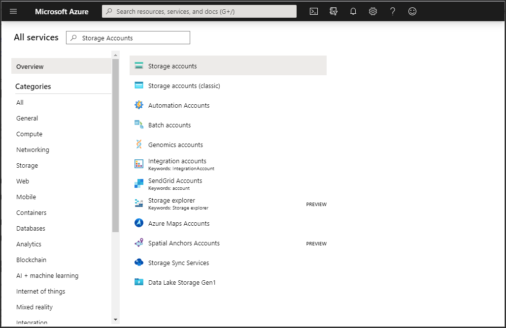
The list of available storage accounts is displayed.
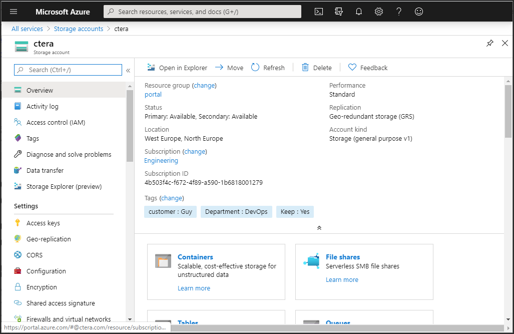
2 Either create a new storage account for the image or click the storage account to use for the image.
3 The storage account details are displayed.
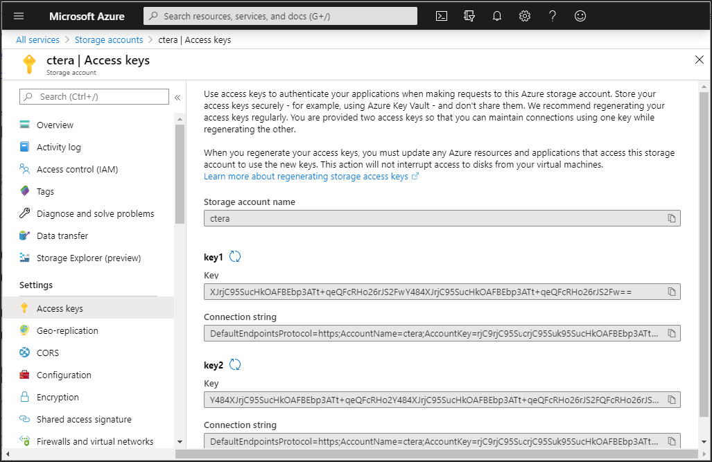
4 Click Access Keys and note the Storage account name and the Key 1 key value.
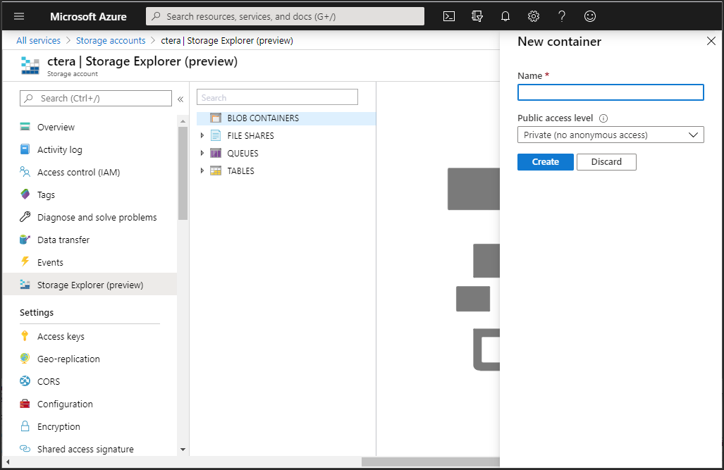
5 Click Storage Explorer (preview) and right-click BLOB CONTAINERS and select Create blob container.
The New container blade is displayed.
6 Refresh Azure, expand BLOB CONTAINERS and right-click the portal image blob container and click Get Shared Access Signature.
The Shared Access Signature blade is displayed.
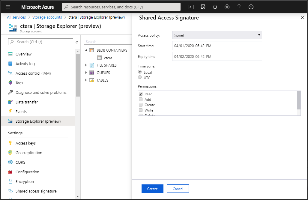
7 Set the permissions and click Create.
8 Copy the URI that is generated and save it.
The URI includes a shared access key.
To get the image:
AzCopy.exe cp "<source_uri>" "<destination_uri>"
source_uri – The source URI from CTERA Support.
destination_url – The destination URL from 8.
The image is copied to the container. This can take some time.
To create the CTERA Edge Filer (Gateway) instance in Azure:
1 Log in to your Azure portal and access the Images service to display the image obtained from CTERA support at http://support.ctera.com.
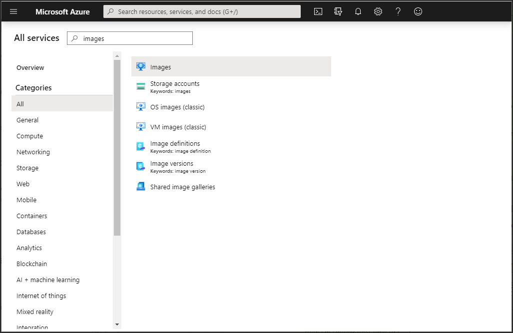
The list of available images is displayed.
2 Click the image for the CTERA Gateway.
The image details are displayed.
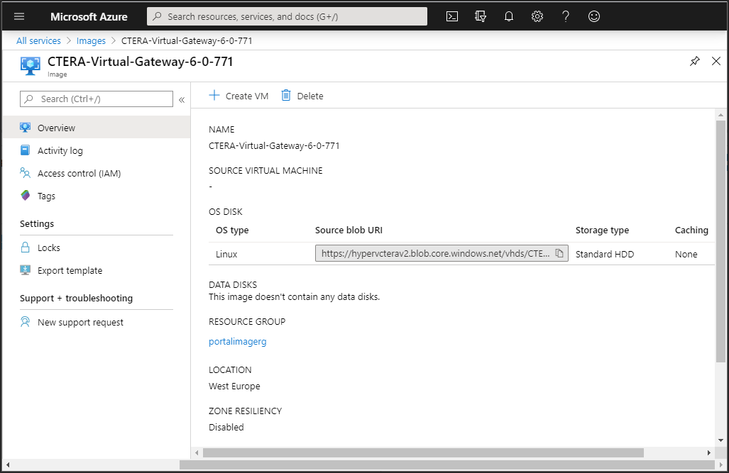
3 Click Create VM.
The Create a virtual machine blade is displayed.
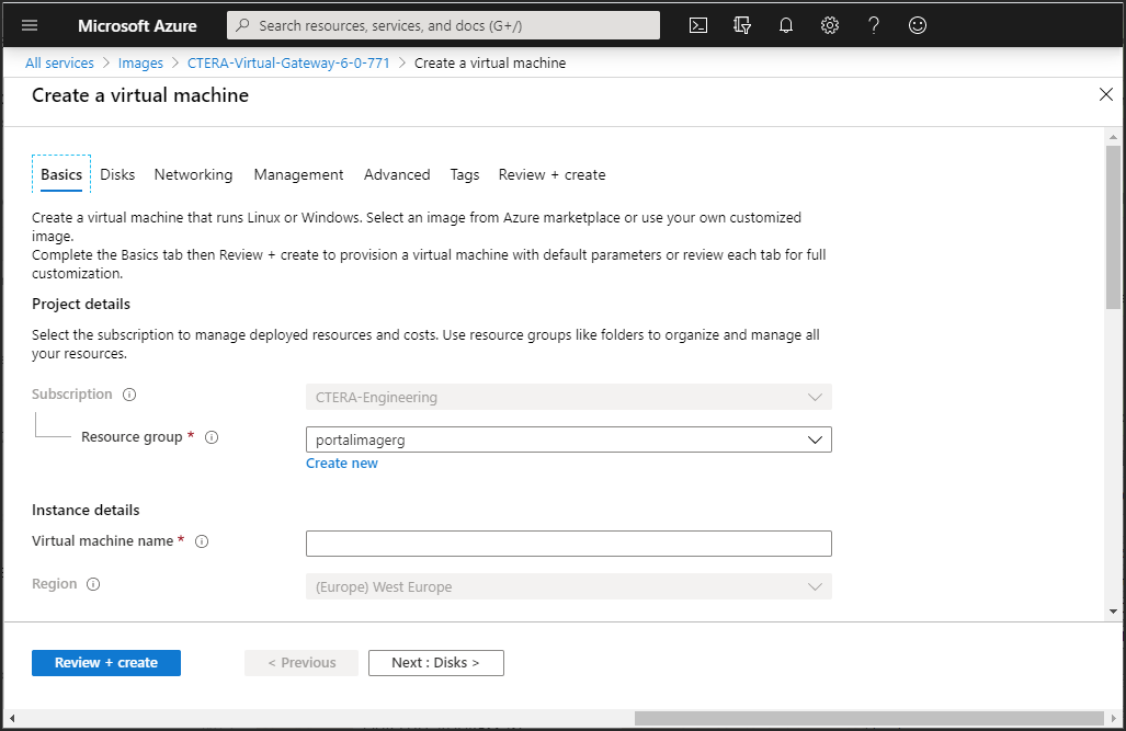
4 Enter the following in the Basics tab for the virtual machine.
Resource group – The resource group to be used. The resource group must use premium storage.
Virtual machine name – A name to uniquely identify the virtual machine.
Region – The region to host the virtual machine.
Size – Click Select size to specify the size of the storage used for the gateway software.
The Select a VM size blade is displayed.
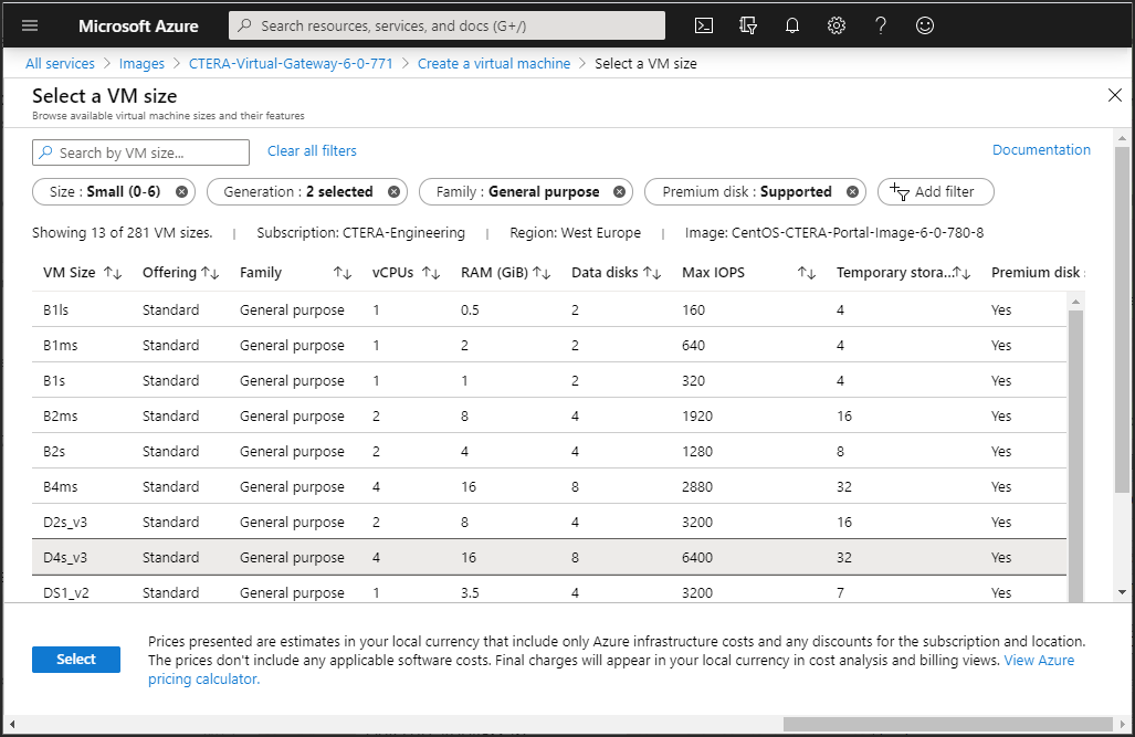
i Select a VM that matches your requirements. The size you select should be dependent on the license.
License | Maximum vCPUs | Maximum Memory |
|---|---|---|
EV16 | 4 | 8GB |
EV32 | 8 | 16GB |
EV64 | 16 | 32GB |
EV128 | 32 | 64GB |
The gateway software requires less than 1GB SSD storage. CTERA limits the number of data disks for a gateway to 16.
ii Click Select.
Authentication type – Choose either SSH public key or Password. The tab changes dependent on this choice to enable entering the SSH public key or a password and confirmation password. Make a note of any password entered, as it is used to log on to the gateway instance.
Username – A name to access the virtual machine. This is an administrator name that can access the gateway.
Note: Once the virtual machine has been fully configured, CTERA provides a user name and password, but this user name can also be used.
Public inbound ports – Choose the None option. Inbound and outbound ports will be added later.
Leave the other values with their defaults.
5 Click the Disks tab, or click Next: Disks.
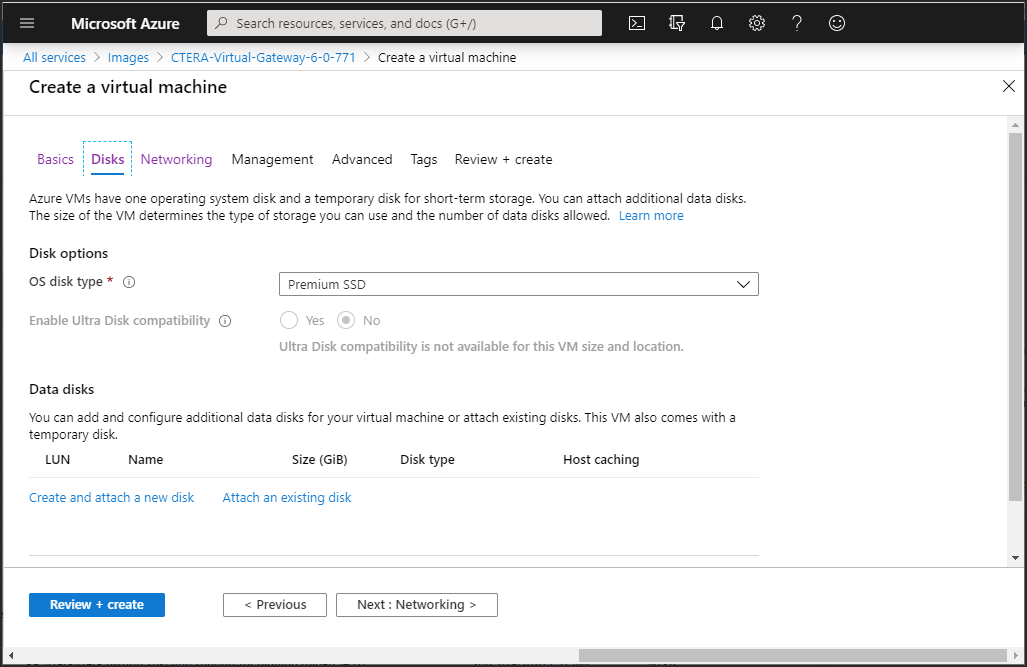
6 Set the OS disk type.
7 Under Data disks, click Create and attach a new disk.
The Create a new disk blade is displayed.
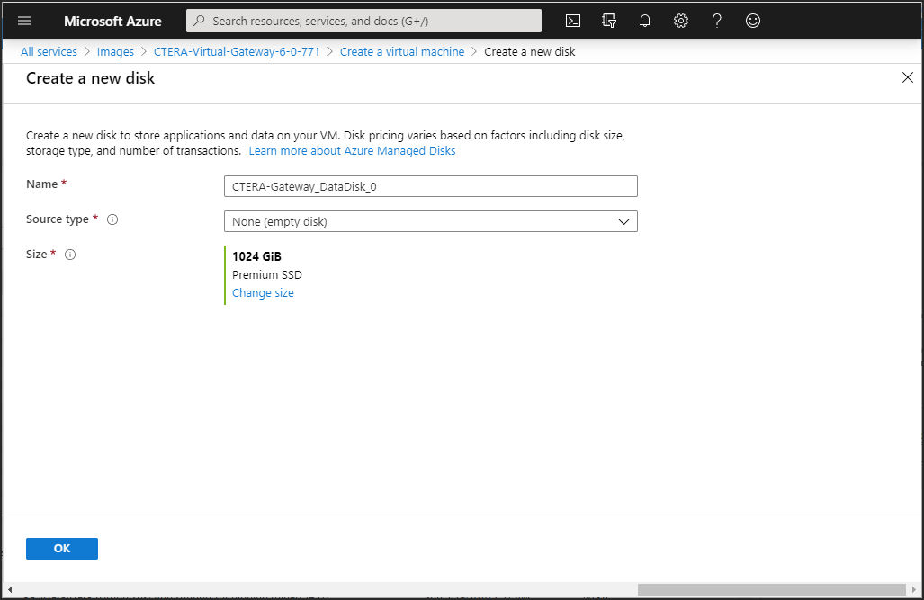
8 Enter a unique name to identify the disk.
9 Click Change size and enter the storage type and size of the disk. You can add more than one disk, up to the number allowed for the size of virtual machine selected in step 4. When configured as a Caching Gateway, CTERA recommends storage at least 20% of the Portal Global Name Space. The maximum storage is dependent on the license.
For an EV16 license the maximum is 16TB.
For an EV32 license the maximum is 32TB.
For an EV64 license the maximum is 64TB
For an EV128 license the maximum is 128TB.
Click OK.
10 Leave the Source type value as None and click OK.
11 Click the Networking tab, or click Next: Networking.
12 Set the network and subnet details to access the gateway.
13 Click the Review + Create tab, or click Review + Create.
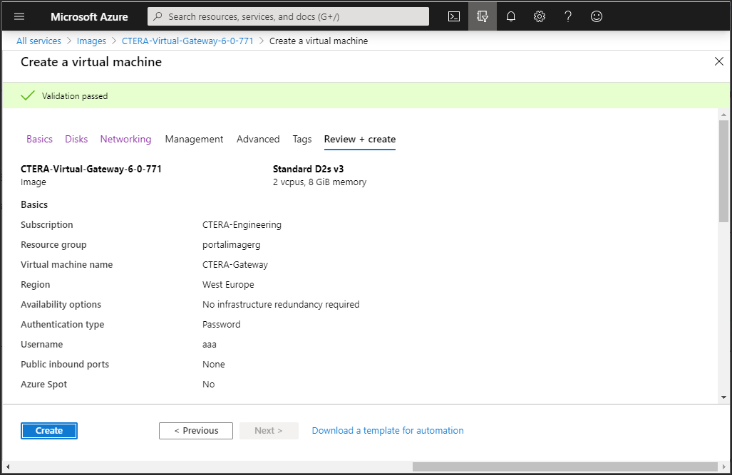
14 Review the virtual machine details and click Create.
The machine is deployed, which can take a few minutes.
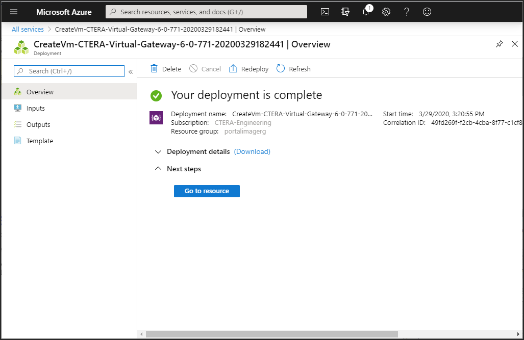
The machine is started automatically.
15 Either, Click Go to resource to display its details.
Or,
In the Azure portal All services pane click Virtual machines, under the Compute service.
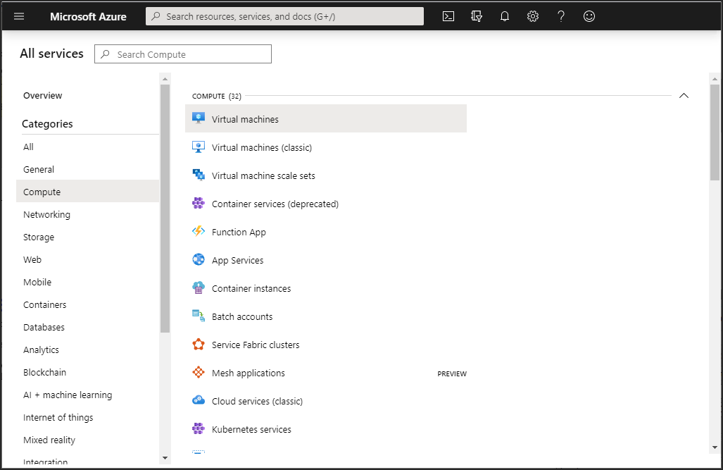
After clicking Virtual machines, the list of virtual machines is displayed.
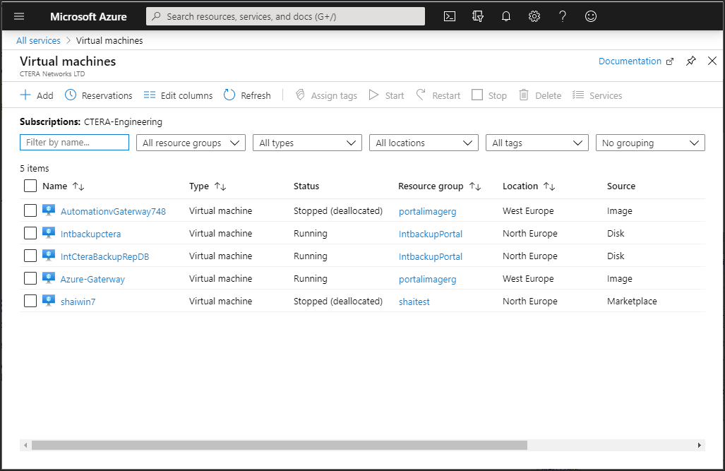
Click the virtual machine to display its details.

The virtual machine includes the OS disk and the added data disks, which are used for the gateway data.
Note the Public IP address.
16 In the options for the virtual machine in the left pane, click Networking, under Settings, to add inbound and outbound port rules.
17 For Inbound port rules tab, click Add inbound port rule.
The Add inbound security rule pane is displayed.
18 Add the following inbound port rules and clicking Add after adding each rule:
Name | Protocol | Port |
|---|---|---|
HTTP | TCP | 80 |
HTTPS | TCP | 443 |
NetBIOS | TCP | 139 |
NetBIOS | UDP | 139 |
AURP | TCP | 387 |
AURP | UDP | 387 |
SMB | TCP | 445 |
SMB | UDP | 445 |
AFP | TCP | 548 |
Rsync | TCP | 873 |
CTTP | TCP | 995 |
19 For Outbound port rules tab, click Add outbound port rule.
The Add outbound security rule pane is displayed.
20 Add the same ports as you added for the inbound security rules (steps 18).
Note: You need to change the Name field, as it was used for the inbound port. For example:
Name | Protocol | Port |
|---|---|---|
HTTP1 | TCP | 80 |
HTTPS1 | TCP | 443 |
NetBIOS1 | TCP | 139 |
NetBIOS1 | UDP | 139 |